Rf Field Strength Meter Circuit Diagram

Pin On Ham Radio

Portable Satellite Field Strength Meters For Dstv Satellite Dish Installations T M I Electronic Circuit Projects Ham Radio Antenna Ham Radio

Pin Di Sender U A

Pin On Rf Measurements Instrument Home Built

Pin On Hamradio

Pin On Tech Stuff

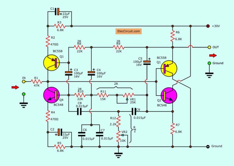
A field strength meter fsm is a very useful circuit to detect and measure the rf signals and their strength.
Rf field strength meter circuit diagram.
Circuit Zone Com Electronic Projects Electronic Schematics Diy Electronics Electronic Schematics Electronics Projects Diy Electronics

Pin On 555

Rf Module 433mhz Circuit Diagram Circuit Diagram Circuit Diagram Electronics Circuit Electrical Wiring Diagram

Pin On Ham Radio

Pin On Electronica Pc

Pin On Next Project To Do

Pin On Sony Led Tv

Pin On Space Between

Pin Di Radio Ht

Pin On Fm

Quality Electronic Kits Electronic Projects Electronic Schematics Fm Transmitters Tv Transmitters Electronic Schematics Electronic Kits Electronics Basics

Http Www Zpag Net Electroniques Radio2 Field Strength Meters Html Electronic Engineering Audio Amplifier Electronics Projects

5 Radio Frequency Circuit Diagrams Eleccircuit Com Circuit Radio Frequency Circuit Diagram

18w Fm Transmitter Electronic Schematics Electronics Circuit Fm Transmitters

Simple Walkie Talkie Circuit Diagram Pdf Circuit Diagram Images Circuit Diagram Electronic Circuit Projects Walkie Talkie

Pin Di N6voa Utoc

Magnetic Field Strength Measurement Using Arduino Arduino Magnetic Field Microcontrollers

5 Radio Frequency Circuit Diagrams Eleccircuit Com Radio Frequency Simple Electronic Circuits Circuit Diagram

Active Antenna Hf Vhf Uhf 3 3000mhz Antenna Ham Radio Antenna Ham Radio

Crystal Radio Detector Receiver High Performance Full Wave Set 6 Db Gain Electronic Schematics Transistor Radio Radio Design

Long Range Cell Phone Detector Using Lm358 Cell Phone Deals Cell Phone Protection Phone Deals
How Does A Transistor Circuit Works Eleccircuit Com Basic Electronic Circuits Electronics Circuit Circuit

Long Range Fm Transmitter Electronics Circuits Hobby Fm Transmitters Electronics Circuit Circuit Diagram

Longwire Match For Sw Receivers Most Shortwave Receivers Use A 50 Ohm Coaxial Input Which Is Not Directly Suitable Fo Fm Radio Receiver Radio Antenna Receiver
Source : pinterest.com
