Revit See Perimeter Wall Through Roof

Solved Wall By Face Flip Orientation Autodesk Community Revit Products

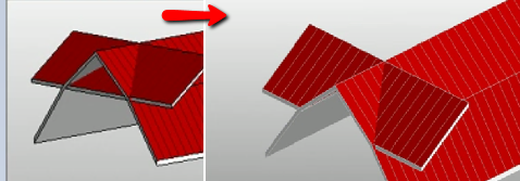
Solved Why Do Roofs Cut Walls When Joined Autodesk Community Revit Products

Room On The Roof Autodesk Community Revit Products

The Cantilevered Mini Parapet Notice That Air Control Layer Continuity Is Achieved By Wrapping The Membrane Over The Buildi Parapet Roof Construction Roof Edge

Borders And Trims For Ceilings In Revit Ceiling Ceiling System Ceiling Design

Attic Floor Insulation Should Extend Over The Top Plates Of Perimeter Walls To Timber Roof Roof Construction Roof Detail

I have been messing around with it for 2 hours but have not resolved how to hide certain roof lines in the model and am unsure how to add them in the places that i want.
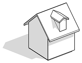
Revit see perimeter wall through roof.
How To Create A Thatch Roof In Revit Micrographics Thatched Roof Thatch Roof

Tutorial Conceptual Massing And Revit Structure 2014 Conceptual Tutorial Illuminati

Detail Warehouse Revit Roof Detail Flat Roof Design Roof Design

Revit Conceputal Massing 04 Wall Roof By Face Revit Tutorial Autodesk Revit Mass

The Masonry Parapet The Thing To Note Here Is That The Concrete Deck Is The Air Control Layer So An Additional One Is Not Parapet Roof Construction Roof Design

Trellis Modelling With Glazing Roof Option Trellis Autodesk Revit Autodesk

Revit Sloped Glazing Youtube

Large Analysis Surface Gap For Gable Roof From Revit Geometry To Energy Model Autodesk Community Insight

Parapet To Flat Roof Junction Detail Drawn In Revit 2015 Parapet Roof Coating Rigid Insulation

Green Roof And Parapet Graphic Courtesy Of Professional Roofing Magazine Roof Architecture Roof Detail Parapet

Roofs Overview Revit Products Autodesk Knowledge Network Roof Autodesk Umbrella

Hickman Permasnap Parapet Wall Coping By W P Hickman Company Roof Architecture Parapet Roof Construction
How To Cut A Hole To A Roof Revit Lt 2018 Autodesk Knowledge Network

Pin By Ovio Sit On Revit Architecture Details Building Construction Home Construction
9 Tips To Understand Revit Roofs Revit Pure

Roof Diseno De Teja Courtain Wall Part 2 Roof Tiles Roofing Roof

Pin By Narin Assawapornchai On Go Green In 2020 Green Roof Roofing Rain Water Collection System
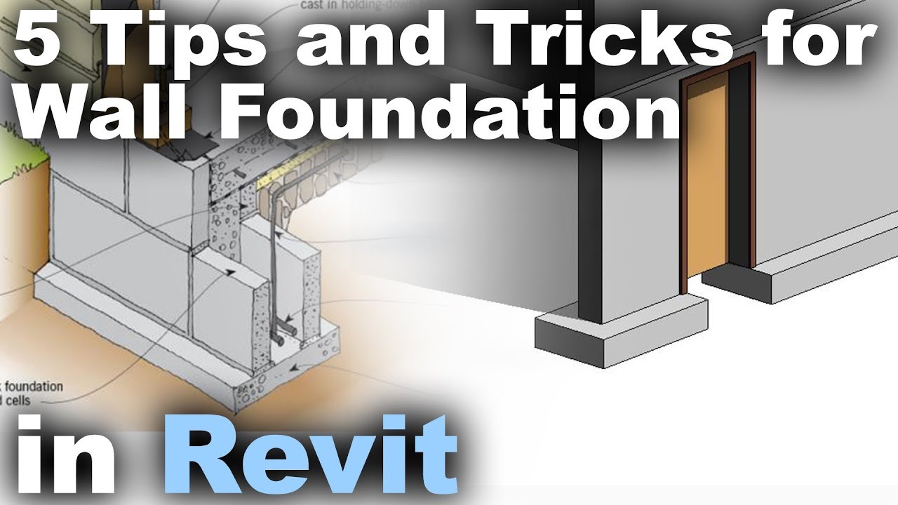
5 Tips And Tricks For Wall Foundation In Revit Tutorial Youtube
Https Encrypted Tbn0 Gstatic Com Images Q Tbn 3aand9gcqgo1kczcdy0vhcurzhsohwmpwenjx4hjgosrbcicvfs0n0mie4 Usqp Cau

Curtain Wall Construction Construction Details Architecture Architecture Details Curtain Wall Detail

Pin On Architect S Data
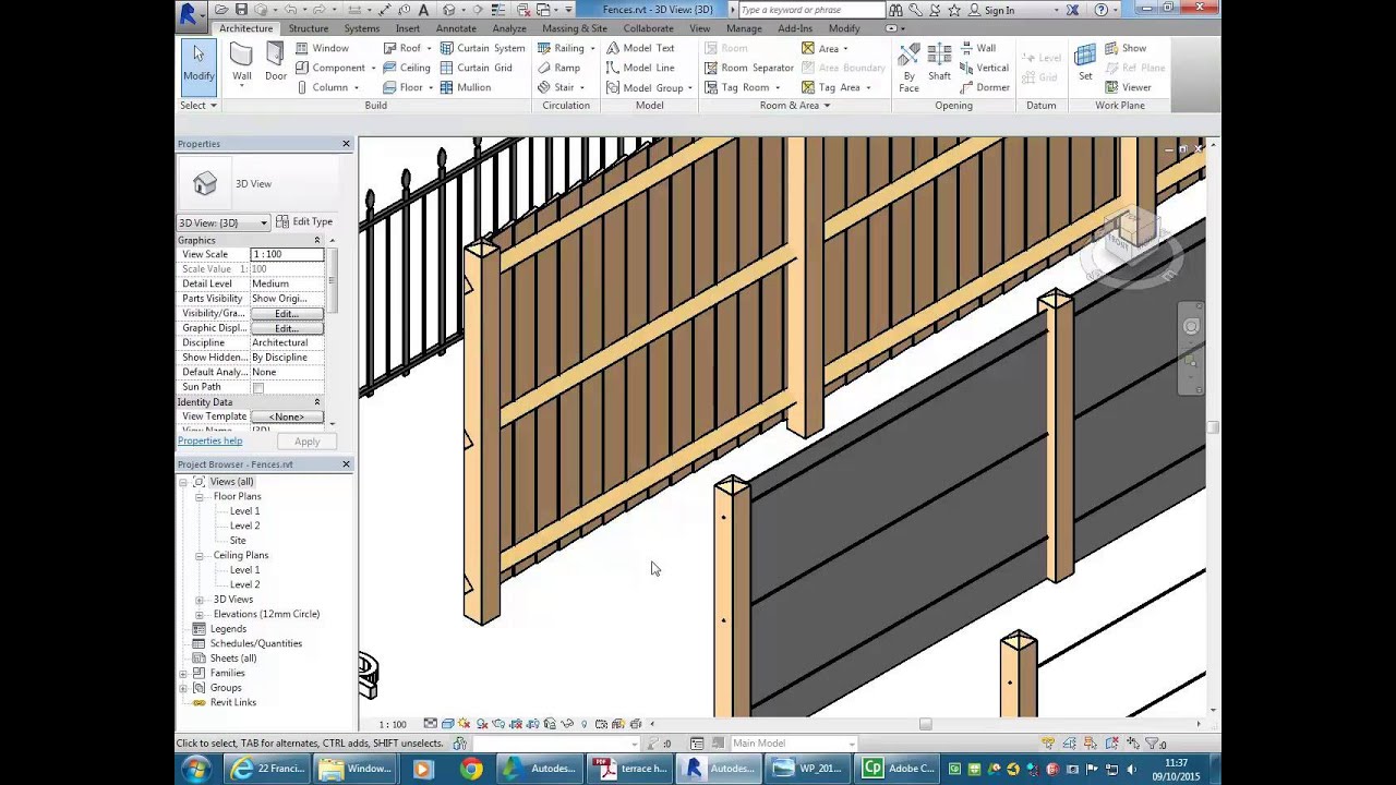
Revit Confined Dwelling 05 Adding Fences Youtube

Gutters And Cornices For Frame Walls Cubierta Arquitectura Sistemas Constructivos Cubierta De Techo

Noun Fortification A Defensive Wall Or Elevation As Of Earth Or Stone In A Fortification An E In 2020 Architecture Details Roof Construction Architecture Building
Source : pinterest.com
