Reverse Engineering Sheet Metal Parts Using Solidworks

Power Surfacing Re Reverse Engineering For Solidworks Tutorials Solidworks Tutorial Solidworks Engineering

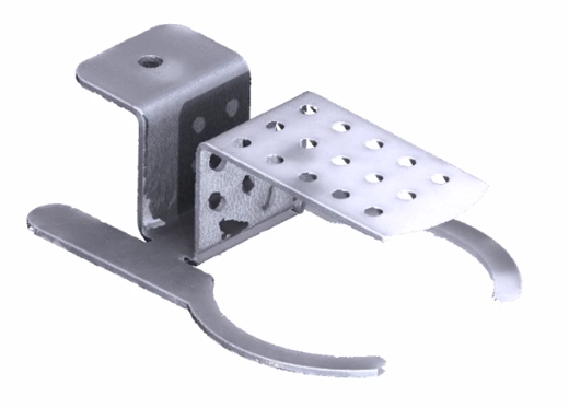
Reverse Engineering For Industrial Machinery To Remanufacture The Sheet Metal Part Mechanical Engineering Design Engineering Mechanical Design

Solidworks Tutorial Design And Assembly Of Ball Bearing In Solidworks Solidworks Solidworks Tutorial Solidworks Mechanical Engineering

Solidworks In Depth Reverse Engineering Products

This Is A Simple Calculator To Help You Calculate Bend Deductions And To Help You Reverse Engineer The Best Sheet Metal Metal Bending Sheet Metal Fabrication

Production Ready Sheetmetaldesign Using Solidworks Metal Design Mechanical Engineering Design Mechanical Design

Along with part assembly and 2d drawing functionality specialized tools are included for sheet metal weldments surfacing molds product configuration design analysis dfm and cam.
Reverse engineering sheet metal parts using solidworks.

Reverse Engineering Sheet Metal To A Flat Pattern Youtube

Pin On Reverse Engineering Services

Solidworks Tutorial How To Make Hydraulic Pump In Solidworks Solidworks Solidworks Tutorial Mechanical Design

Solidworks Tutorial For Beginners Learn How To Design A Part 08 Solidworks Tutorial Solidworks Technical Drawing

Take A Tour Of The New Bikecad Ca Website And Learn About Bikecad And Bikecad Pro Bikecad And Bikecad Pro Require Java Solidworks Tutorial Solidworks Tutorial

Pin On Reverse Engineering Services

Pin On Mechanical Engineering

Solidworks Tutorials Q A How Do I Create A V Shaped Sheet Revit

Solidworks Tutorial How To Draw A Coke Bottle Tutorial45 Solidworks Tutorial Solidworks Coke Bottle

Solidworks Tutorial Solidworks Equation C C

3d Laser Scanning To Simplify Reverse Engineering Tasks Engineering Mechanical Engineering Design Mechanical Engineering

Outsource Reverseengineering Of Products For Enhanced Quality And Accuracy Engineering Engineering Consulting Mechanical Engineering
Reverse Engineering Sheet Metal To A Flat Pattern Cimquest Inc

Sheet Metal Design Guide Calculate Bending Allowance Accurately Sheet Metal Sheet Metal Work Metal Design

Pin On Mechanical 3d Modeling Services

Solidworks Tutorial Sketch Stapler In Solidworks Solidworks Youtube Solidworks Solidworks Tutorial Tutorial

Pin On Mechanical Engineering And Design

Pin On Solidworks Tutorials For Beginners
Https Encrypted Tbn0 Gstatic Com Images Q Tbn 3aand9gcrfyhjkkzsh Mmejghngulhp0v3cwvl5vs5cf3i3 Mn8a5xrcvi Usqp Cau

Using Bend Notes For Sheet Metal Design In Solidworks 2013 Solidworks Metal Design Design

Pin On Sheetmetal Cad Cam

Pin By Achmad Chusnadi On 3d Modeling Practice Mechanical Engineering Design Mechanical Design Engineering Design

Pin On Guide To Solidworks For Beginners

Pin On Mechanical Engineering
Source : pinterest.com
